


The hall effect sensor (globe position sensor) is more than likely something you know little about, and I didn’t either until all three of the lights on my Litter-Robot 3 were flashing at me. At the time, I had absolutely zero clue what was happening, nor did I know that there were different combinations to tell me of the specific problem.
In this article, we will examine the hall effect sensor, its role in the function of your Litter-Robot 3, and how to ensure it is correctly installed.
HALL EFFECT SENSOR
This sensor works in conjunction with the magnets installed in the globe and the number of motor revolutions during cycling. When correctly installed and the globe rotates through a cycle the micro sensors on the ends of the 2 sets of wires identify when the two sets of magnets installed in the globe pass by for both the dump and home position.
If all three of the lights are flashing (in one of three combinations), it is an indication of a globe position fault.
- Blue, then yellow, then red (Flashing sequentially, one light at a time): This means the unit cannot find the dump position. It will continue to function in automatic mode but needs review.
- Red, then yellow, then blue (Flashing sequentially, one light at a time): This means the unit cannot find the home position. It will continue to function in automatic mode but needs review.
- Blue and yellow and red(All three lights flashing simultaneously): This means the unit cannot find the dump or home position. The unit will not cycle automatically and needs review.
There are several checks to complete for this fault to be resolved.
- Check that the globe is securely installed, with the black key sitting in its slot on the base.
- Check that you have the correct 15V power supply, and check the cord is not kinked or nicked at any point.
- Check the globe, that the litter is not over filled (approx 4.5kg of litter), that there are no obstructions that are preventing the globe from rotating, and that there is no debris on the outside of the globe.
- Check the base and ensure that this is free of debris and the seal strips are in place and clean.
- If you have unscrewed the globe, you may have lost the magnets. For information on this issue, you can check out this article.
- If you have unscrewed the motorwell, the hall effect sensors maybe out of position and you will need to grab your trusty screwdriver and venture into the motor well again to review this.
ENTERING THE MOTOR WELL
With the bonnet and globe removed you will need to loosen the 5 screws that hold the motor well cover in place. Using a pair of pliers you should be able to lift the motor well cover up. NOTE that the main board is attached to the motor well cover, so you do not want to pull with too much force.
To separate the main board from the motor well cover you will need to gently push on the buttons whilst wiggling the cover.
motor well cover separating main board


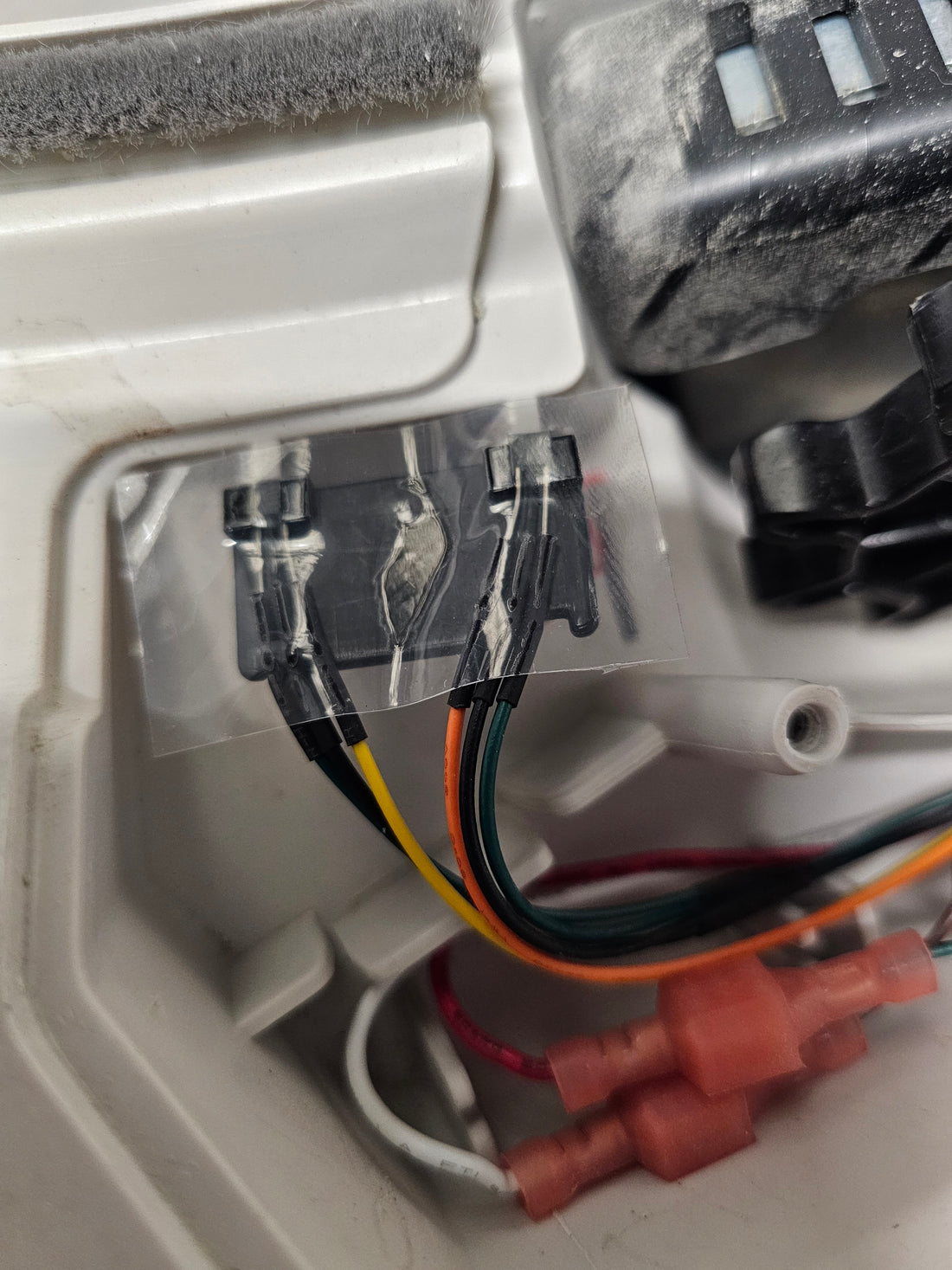
Once inside the motor well you will be able to locate the hall effect sensor on the front left side. There are two sets of three wires each with a micro sensor (the left with green, black and yellow and the right with orange, black and green), both of which are fitted to a black plaform to position them correctly.
There should be a piece of waterproof tape firmly in place covering the exposed wires. The tape acts like an umbrella, protecting the exposed wires from wayward urine or moisture that may make its way into the motor well and cause corrosion. If you are replacing the tape, make sure you take care removing the existing tape and install the new piece flat, not folded over the ends of the sensors.
correctly installed hall effect sensor

IDENTIFYING THE FAULT IN THE MOTOR WELL
Should your hall effect sensor look like any of the pictures below or you notice that the exposed wires have separated from the sensors, you have located the fault.
NOTE: If the exposed wires have broken from the sensors you will need to replace the wiring harness (make sure you keep the platform as this is not included in a wiring harness purchase). If you need any assistance with warranty or support please email support@catevolution.com.au with photos for review..

Picture 1: Shows that the black platform (which holds the sensors) is missing. This would only have occurred if someone had previously entered the motor well and removed it. You need to locate the platform and reinstall the sensors. If you can not locate it you will need to email support@catevolution.com.au for a replacement (if available). Platforms are not included in wiring harness purchase.
Picture 2: Shows that the sensors are on the black platform correctly but the platform is not in the pillars in the motorwell. When you look closely at the bridge you will note two legs on one side (which fit securely into the motor well pillars).
Picture 3: Shows the hall effect sensors sitting forward out of the pockets on the platform, with no sticky tape to keep them in position. You will need to refit the sensors into the pockets and apply new tape. If you are not sure the sensors are correctly aligned, review the pockets. The left pocket has a narrow top opening and wide bottom and then right pocket has a wide top opening and narrow bottom (as pictured below).
IMPORTANT: Be gentle when handling the 2 sets of wires with sensors. The exposed wire section should not be bent, and if you look closely, you will notice that there is only one way the shaped sensors can be inserted into the small pocket on the platform to help with installation. A little tilt helps ease the exposed wire section into the platform pocket top, and the black sensor can then be drawn into the actual pocket by gently pulling on the wires, backing the sensor into the shaped pocket (pictures below for reference).

When you look closely at the ends of the sensors and you will note that they have a narrow and wide edge.

The green, black and yellow wire group will fit into the left hand pocket, and the orange, black and green wire group will fit into the right hand pocket.

You have successfully identified the fault and reinstalled the sensors into their position in the motor well, with the protecting tape. The motor well cover can be secured and the globe and bonnet place back into postion for a return to your no-scooping lifestyle.
PROTIP ensure the tape is in place in the motorwell to keep the wires from being picked up by he black gear wheel when refitting the cover.
